Air ventilation duct
Ventilation ducts of rail vehicles reach dimensions of several meters in length and often have complicated geometries, as they are placed in the remaining free space between the metallic vehicle structure and the interior trim. This leads to duct geometries with multiple deflections and cross-section changes, which in turn results in increased pressure losses.
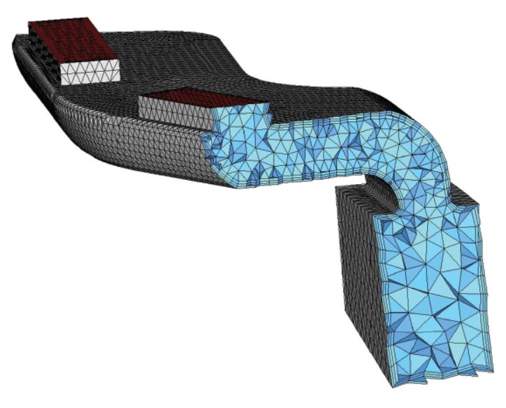
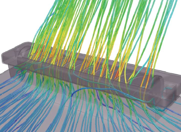
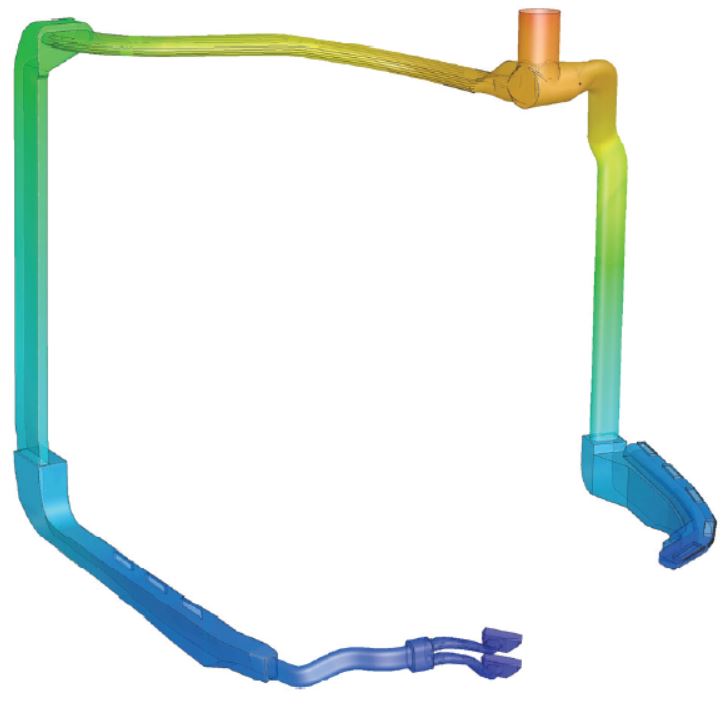
The images show display a section through a CFD model of a ventilation duct meshed with tetrahedron and prism cells, a detailed model of an adjustable exhaust nozzle with streamlines, and the ventilation duct of a driver’s cab.
With a flow simulation, statements on pressure loss and the flow velocities in the duct can be made quickly and even before the duct has been manufactured (and possibly tested). Furthermore, problematic areas in a ventilation duct (system) can be identified more easily and quickly with a simulation than with complex measurements.
Contact

Dr. Walter Vonach
vonach@cae-sim-sol.at
+43 1 974 89 91-13