Zahnimplantat

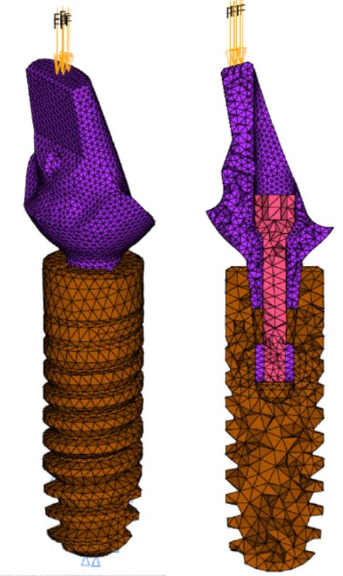
The finite element model was based on CAD data from the three different parts, i.e. the implant, the connecting screw and the post. The brown part represents the titanium implant including the screw convolutions. The purple part represents the post. The cross-section of the model is depicted showing the implant (brown), the connecting screw (pink) and the post (purple).
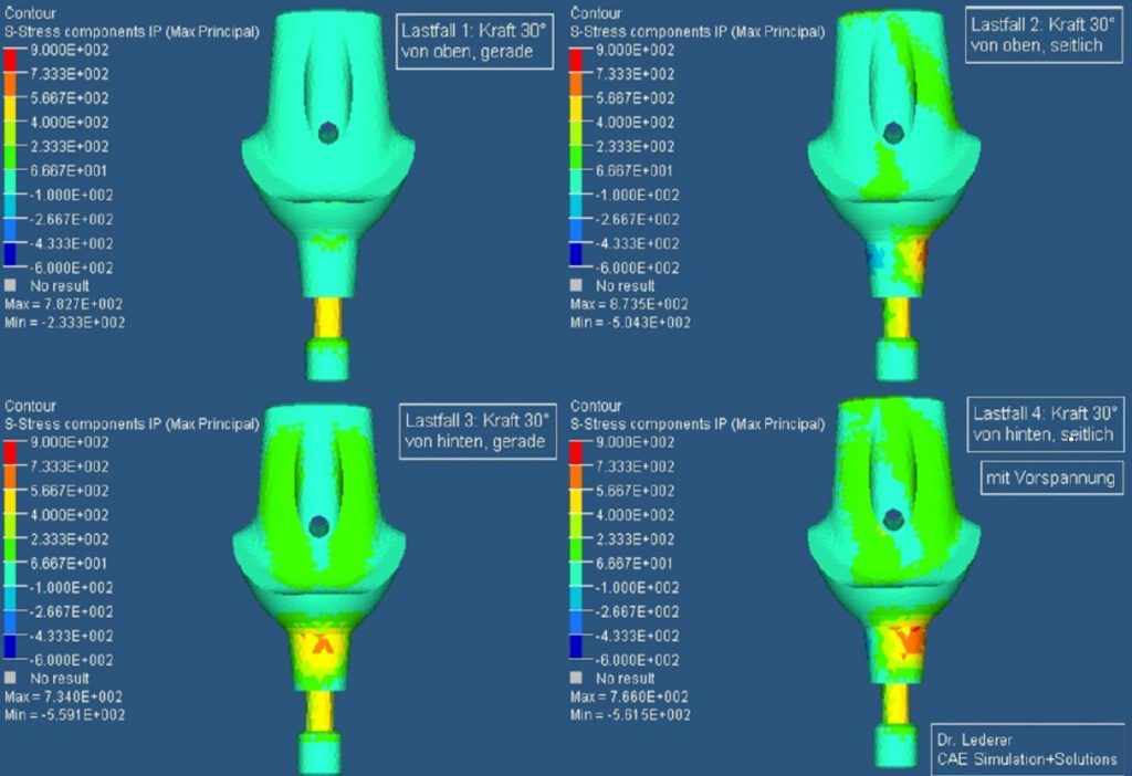
The figure below depicts the results of four load cases for a titanium post. The axial loading yields the lowest stresses. The bending loads, i.e. a saggital bending and a transversal bending of the post, yield maximum tensile stresses of 600 MPa at the post neck. The highest tensile stresses with up to 800MPa occur for load case 4, i.e. the combined bending.
The results show that the titanium post withstands a static load of 150N for all the assumed load cases. The calculated stresses for bending loads however yield maximum principal stresses of 600 – 800MPa. These values are above the fatigue limit of the used titanium alloy which is about 400MPa. A comparison of the results for the titanium and the CERCON post show only small differences. The mechanical behaviour of both posts is very similar. The stresses in the system are governed by the geometrical layout of the post which is similar for both designs.

